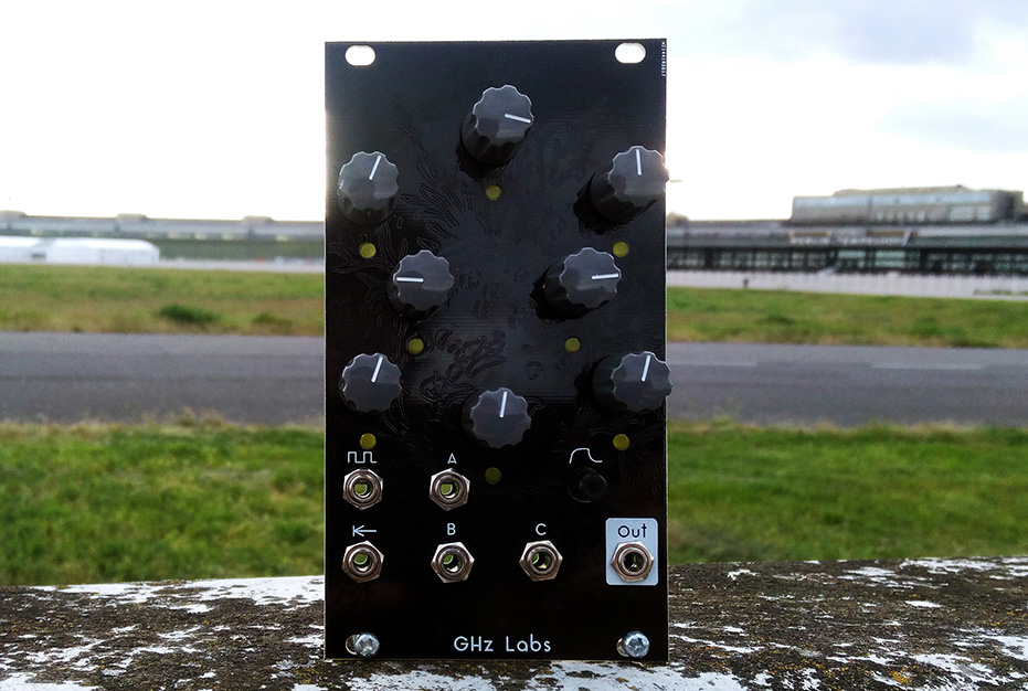
The second module designed for the workshop at Common Ground and part of the GHz Labs series, was an 8-step CV sequencer. With inputs for clock, reset, 3 logic OR-ed step inputs and glide control. Utilizing the step inputs with a clock divider or any gate source can further create more complex, non-linear sequences.
Again inspired heavily by the tutorials put together by Peter Edwards from Casper Electronics.
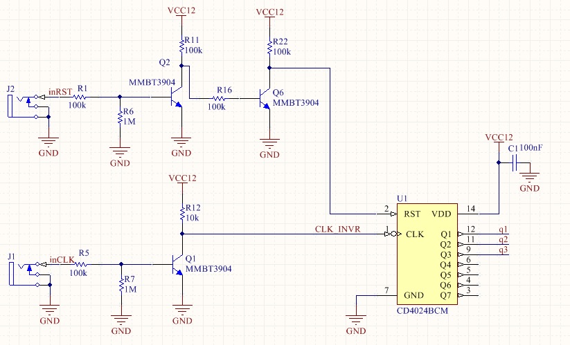
The sequencer is based on two very useful ICs, the CD4024 Ripple-Carry Binary Counter and the CD4051 Analog Multiplexer. The Binary Counter acts as a “step select” for the Multiplexer, that routes one of the 8 potentiates from it’s input to it’s output.
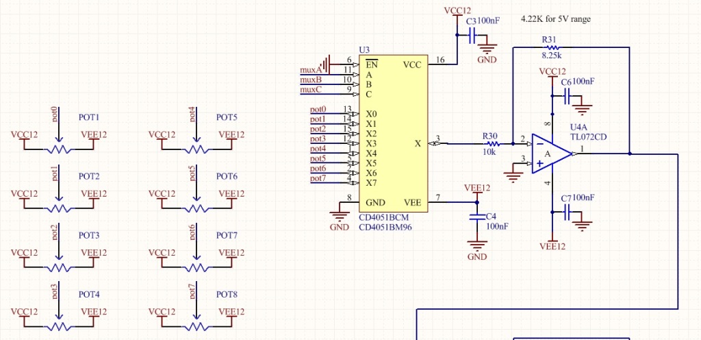
The potentiometers are configured as voltage dividers, giving anything from -12 to +12 volts. Followed by an attenuation circuit to prevent the Op-Amp from saturating and finally reaching the glide (or slew rate limiting) circuit.
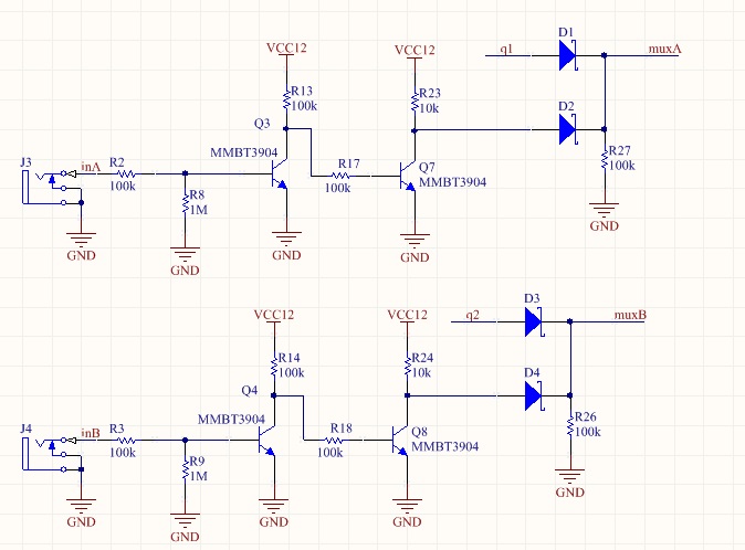
The A, B and C inputs are connected to the Multiplexer channel select inputs, OR-ed together with the Counter outputs through diodes. So that the steps can arbitrarily be switched around.
The first iteration of the design used two +/- 5 V regulators, but I decided to “simplify” the circuit and run everything straight off the +/- 12 V rails. Which ended in a transistor clutter to shift the clock and trigger levels from 5V to 12V.
As the Counter and Multiplexer now run on the 12V rail, the VIH Min. (minimum logic level for a high signal) would be something above 7 V. This would not quite work with Eurorack 5V trigger levels. In the next revision I might try to move the logic level shifting to a later stage of the Multiplexer Input to reduce the number of transistors needed.
Let me know if you like this design in the comments down below!
You can find the full schematics and BOM files here. And the accompanying website.